The Fundamental Misinterpretation of Hypertherm Gas supply Specifications
- Armands Sakne
- Nov 10, 2025
- 7 min read

Updated: Nov 19, 2025
When most people in the compressed air industry read a Hypertherm manual, they see something familiar: “7.5 bar — 118 SLPM — ISO 8573-1 Class 1.4.2.”
To them, it looks like any other pneumatic specification — a standard requirement for an industrial air tool. So, they size the compressor, receiver, and dryer as they would for an angle grinder or a sandblaster. This is where the misunderstanding begins. Hypertherm plasma systems operate far beyond pneumatics.
It's a closed-loop thermodynamic energy unit, where every molecule of gas becomes part of a high-temperature electrical plasma field.
The gas entering the console is not there to move a piston or drive an actuator. It becomes part of the plasma itself, the working medium of a high-energy thermodynamic reaction. That means the same rules that apply to a pneumatic grinder or a valve do not apply to a plasma system. Pressure and flow are only the visible numbers.
What actually drives performance is molecular density, gas composition stability, and dynamic balance between plasma and shield lines.
With cold air molecules are packed closer together. Pressure remains the same, molecular density can be dramatically different.
Pneumatic vs Thermodynamic Thinking.
In pneumatic engineering, the goal is to deliver pressure and flow. Losses in the pipeline cause slower tools or weaker force, but the process still works.
Recipe for disaster, simply install for HiDefinition plasma cutting machine air compressor with input specification: 7.5 bar — 118 SLPM — ISO 8573-1 Class 1.4.2..
What Hypertherm specification in the manual really means — 7.5 bar, 118 SLPM, ISO 8573-1 Class 1.4.2.?
This is a reference to internal process conditions inside the gas console, not the external air supply.
There is a general assumption that when the air reaching the gas console has already passed through a properly sized infrastructure that can maintain stability in molecular density under load.
Molecular density = Kinetic and thermal properties of plasma arc.
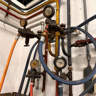
In the picture below, a real-time illustration of when the vendor exactly supplied to the customer — 7.5 bar, 118 SLPM, ISO 8573-1 Class 1.4.2. compressor system. Real cases for HPR and XPR plasma cutting systems.


Building an Air Supply System for Plasma.
Most compressor and infrastructure vendors don’t make this distinction correctly. They sell systems that “meet the pressure and flow numbers,” unaware that those numbers describe steady-state lab conditions, not real factory behaviour.
They think in litres per minute and bars. But the plasma torch “thinks” in molecules per second.
A compressor sized for 120 L/min at 8 bar might run a pneumatic wrench perfectly. However, the same setup on a Hypertherm HPR400XD or XPR300 will deliver machine struggle, even if the gauge shows precise pressure.
Why? Because the mass of gas reaching the swirl chamber is lower, the air is hotter, less dense, and fluctuates with every pierce and cut cycle.
The result: angularity, part geometry or dimension problems, and short consumable life.
Operators and shop mechanics blame the machine components for poor cut quality; in reality, the problem is the misunderstanding of basic physics.
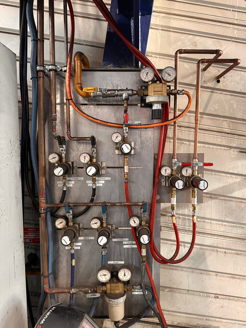
Both manometers at CG1 and CG2 should show identical gas pressures.


How Density Drops in Real Life. Let’s translate this into something every service technician has seen.
Hypertherm assumes that with perfect conditions, air must enter the gas console at 20 °C, 0 % humidity, and 8.0 bar absolute pressure.
Under those ISO conditions, the air density is about 9.6 kg/m³ — that is the reference Hypertherm uses when they write 7.5 bar @ 118 SLPM in the operator's manual.
Now step into the real world, where there are no two factories alike.
One shop runs at 35 °C with humid coastal air; another sits 800 m above sea level; one uses a piston compressor with a small receiver, another a screw unit with a chiller; one has 10 m of 1″ pipe, another 100 m of 3/8″ hose.
On paper, they all show 8 bars. In reality, each of them delivers a completely different molecular density to the plasma console.
That’s why identical Hypertherm machines can behave so differently across sites.
The torch doesn’t adapt to altitude, room temperature, or piping geometry. System demands the same internal conditions everywhere, wherever machines are installed in the world: 7.5 – 7.9 bar inside the console, with precise molecular density and composition.
Every deviation outside that narrow thermodynamic window changes the arc itself. Lower density means lower energy in the plasma arc. A few percent less mass flow translates into visible angularity and failing True Hole or True Bevel process execution.
The problem is that each factory has its own atmosphere, but the plasma process expects just one — the ISO reference atmosphere Hypertherm designed it for.
And the only way to recreate that, no matter the temperature, altitude, or compressor type, is to design the air infrastructure so that the gas console always experiences the same molecular conditions Hypertherm used in testing.
Unknown age of pressure regulators. Real work conditions of gas pressures for XPR and HPR.


Why Hypertherm Is Technically Right — and Why the Industry Still Gets It Wrong.
The confusion doesn’t come from Hypertherm’s documentation. Every number in those tables is correct. The misunderstanding comes from where those numbers belong.
Hypertherm defines what the gas console must receive, not what the compressor must deliver. Hypertherm measures performance inside a controlled ISO environment, where all variables like pressure, temperature, humidity, and flow resistance are accounted for during testing.
That’s why the values in the manual describe a final thermodynamic condition, not an installation guideline.
In the field, these variables are rarely taken into consideration. The distance between the compressor and gas consoles, the receiver tank size and dryer configuration, air temperature, humidity, and gas supply pipe diameters. Infrastructure is changing the gas supply long before it reaches the torch. Even the pressure regulators, the key stabilizing elements of the entire chain, are often treated in welding similar manner.
In most factories I visit, the main air line still relies on a single 10- or 15-year-old regulator, originally installed for general shop use. Its response time, hysteresis, and calibration drift are far outside the tolerances required for HiDefinition plasma system.
All pressure regulators should be periodically tested and calibrated in certified metrology labs, just like any other process-critical component. Pressure regulators must be checked at least every five years.
Yet, few companies do this. So when arc voltage or angularity instability appears, the cause is rarely the machine itself — the reason is the slow, untested, ageing pressure regulator.
That is why Hypertherm’s specification is not wrong. It’s complete within its own controlled context, but incomplete once applied without control. The field reality is that most systems were built by pneumatic logic and never validated thermodynamically.
The number 7.5 bar is therefore a destination, not a setting. To reach it, you don’t only raise pressure — you must stabilize the path to gas consoles.
Some very nice 1st stage gas supply setups.


How to Recreate ISO Conditions in the Field.
To make a Hypertherm system perform in every factory, we must stop copying the numbers and start recreating the environment the machine requires.
That means restoring the same molecular stability, pressure balance, and temperature control that exist inside Hypertherm’s test cell — but under real industrial conditions.
It starts with a reserve of enough compressor and receiver capacity to keep the gas console pressures stable during piercing and cutting. Pressure on a gauge means little; only constant mass flow keeps the plasma dense. A screw compressor with stable FAD(Free Air Delivery), a large receiver, and short piping form the base of this stability.
Next comes temperature and purity stability. Air from the dryer must stay clean, cool, and predictable. Dry air alone is useless if its temperature and dew point shift. When the outlet conditions remain almost identical year-round, the system finally mirrors ISO behaviour.
Then comes pressure regulation — the part that most systems neglect. The pressure regulators are the brain of the gas chain. A proper setup uses two stages:
First Stage: A Pressure regulator before the machine to absorb the compressor's wide pressure swings.
Second Stage: Precision regulator near the gas console for fine, fast control.
Both should be regularly tested in a metrology lab; a 5-year-old, unverified regulator is a silent source of infinite cut quality problems.
Plasma and shield gases must move together, under equal pressure, equal timing. If one line lags or drops, the swirl process technology in the torch body collapses, and so the arc geometry loses shape. When both are synchronized, we can expect stable cut quality repeatability.
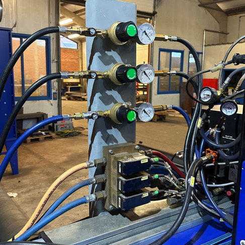
Custom 2nd stage installations by customers, following personal recommendations.


What Works, What Fails, and What to Watch For.
After many installations and machine audits, one pattern repeats itself: plasma systems cut quality rarely fail because of the plasma hardware — it fails because of air systems designed for pneumatics.
Here’s what never goes wrong:
Oversizing the compressor and receiver. You can’t go wrong with more air reserve. A system with an extra FAD four times the capacity and a 500–1000 L tank will be able to deliver air molecular density.
Short, wide, and cool piping. Every meter of 3/8″ hose is a silent density killer. Keep the main line ½″ or larger, under 25 m, and away from heat. It costs a little more but removes half of the “mystery problems.”
Two-stage pressure regulation. Never trust a single regulator for a precision process. The combination of a coarse stabilizer before the machine and a fine regulator by the console gives pressure that behaves like a laboratory line, not a workshop one.
And here’s what causes trouble every time:
Relying on the gauge. Static 8 bar means nothing. Always log live pressure under flow — you’ll see the truth the gauge hides.
Old or untested regulators. Springs age, diaphragms stiffen, and calibration drifts. A regulator that hasn’t been verified in ten years is no longer a precision component.
Shared factory air lines. Mixing plasma with grinders, sandblasters, or paint guns is a recipe for unstable density. Dedicated line = stable process.
Humidity ignored. Compressors that “feel dry enough” rarely are. Moisture shifts molecular density faster than pressure loss, and True Hole feels it first.
And finally, what to remember:
Hypertherm did its part and defined the physics. The problem is not the number in the manual; it’s everything between the compressor and the gas console. When the air system is built like a pneumatic tool network, the plasma behaves unpredictably. When it’s built like a thermodynamic circuit, it behaves exactly as the engineers intended.
Plasma doesn’t cut with pressure — it cuts with molecules. Build a system for the molecules, and you’ll never miss.
How I Start Every Audit
Whenever I enter a workshop, no matter what the complaint about the machine is, cut angularity, consumable life, or general technology failure, I always start at the same place: the gas supply system.
The condition of the gas supply tells everything about the machine and the people maintaining it. If the compressor, pressures, and regulators are correct, the rest of the system usually is too. If the gas side is a mess, the machine will always follow.
Real success stories.


Comments